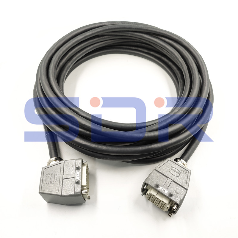
The KAWASAKI X3 Encoder Cable is a specialized high-performance Cable designed for precise signal transmission between encoders and control systems in industrial automation. Engineered with robust materials and advanced shielding technology, it ensures reliable data transfer in demanding environments. The cable is specifically compatible with KAWASAKI X3 series robots and controllers, providing seamless integration for motion control applications.

Conductor Material: Oxygen-free copper (OFC) with 24 AWG gauge, providing low resistance (≤0.08 Ω/m) and high conductivity
Insulation: Double-layer fluoropolymer (FEP) insulation rated for 300V AC/DC with a temperature range of -40°C to +105°C
Shielding: Dual-layer shielding (aluminum foil + 85% braided copper) achieving >90dB EMI/RFI protection at 100MHz
Data Transmission: Supports differential signaling up to 10MHz with ≤0.5ns skew between pairs
Connectors: Gold-plated 15-pin D-sub connectors with 5000+ mating cycles durability
Bend Radius: Minimum 8x cable diameter (15mm) for repeated flexing applications
Environmental Rating: IP67 when properly mated, resistant to oils, coolants, and UV radiation
1. High-Speed Signal Integrity: The X3 Encoder Cable maintains signal rise times below 3ns over 15m lengths, with characteristic impedance of 120Ω ±10% to match encoder outputs.
2. Extreme Environment Durability: Testing shows the cable maintains performance after 5 million flex cycles at 0.5Hz with 25mm displacement. The FEP insulation provides dielectric strength >15kV/mm and volume resistivity >10¹⁶ Ω·cm.
3. Precision Timing: Propagation delay is tightly controlled at 5.2ns/m ±0.3ns, critical for multi-axis synchronization. The phase matching between conductor pairs is maintained within ±0.5° at 1MHz.
4. Vibration Resistance: The strain relief system withstands 5-500Hz random vibration per IEC 60068-2-64, with no signal degradation at 5g RMS acceleration.
Industrial Robotics: In KAWASAKI X3 robotic arms, the cable transmits absolute encoder data from joints to the controller with 16-bit resolution (0.0055° angular accuracy). Typical cycle times of 0.5ms require the cable's high bandwidth.
CNC Machine Tools: For rotary tables and linear axes, the cable's EMI shielding prevents interference from spindle drives (often producing >10V/m fields). The 0.1° positioning accuracy demands the cable's low jitter (<5ns).
Automated Assembly Lines: In pick-and-place systems operating at 120 cycles/minute, the cable's flex life exceeds 3 years of continuous operation. The oil-resistant jacket prevents degradation from ISO VG32 hydraulic fluids.
Semiconductor Manufacturing: Cleanroom-compatible versions with low outgassing (<1×10⁻⁶ Torr·L/s·cm²) are used in vacuum robots. The static-dissipative jacket (10⁶-10⁹ Ω/sq) prevents charge buildup.
Packaging Machinery: For servo-driven form-fill-seal machines running at 200 packages/minute, the cable's 0.1mm² conductors handle 250mA continuous current for encoder power supply.
Maintain minimum bend radius of 15mm during routing to prevent conductor fatigue
Use strain relief within 50mm of connectors to prevent solder joint stress
Separate from POWER CABLEs by at least 30mm, or cross at 90° angles when necessary
For long runs (>10m), verify signal quality with eye pattern testing (minimum 70% eye opening)
Ground the shield at one end only (typically controller side) to prevent ground loops
Regular Inspection: Quarterly checks should measure insulation resistance (>100MΩ at 500VDC) and continuity (≤0.5Ω end-to-end). Inspect for jacket abrasion (>20% thickness loss requires replacement).
Cleaning: Use IPA (isopropyl alcohol 99%) on connectors quarterly. For oil contamination, use non-ionic cleaners with pH 6-8. Never use abrasives or compressed air >30psi.
Storage: When not in use, coil loosely (≥200mm diameter) and store at 15-25°C, 40-60% RH. Avoid UV exposure which can degrade jacket material at >50W/m² intensity.
Connector Care: Annually inspect pin retention force (>0.5N per contact) and apply dielectric grease (NLGI #2) to mating surfaces in high-humidity environments (>80% RH).
Signal Verification: Biannually monitor differential signal amplitude (should be 1.0-1.5Vpp) and common mode voltage (<1V). Use 100MHz+ oscilloscope with differential probes.
Symptom: Intermittent Position Errors
Check for shield continuity (<1Ω to ground point). Verify no shield current (>10mA indicates ground loop). Measure skew between A+/A- signals (<2ns).
Symptom: Excessive Noise
Perform FFT analysis on signal - spikes at 10-100kHz suggest inverter noise (add ferrites). Spikes at 1-10MHz indicate poor shielding (check for braid coverage >85%).
Symptom: Cable Heating
Measure current draw (should be <80% of 250mA rating). Check for adjacent heat sources (>15°C above ambient requires rerouting). Verify conductor resistance (<4Ω for 15m cable).